How to Choose the Right Distillation Column Tray in 2026?
Selecting the right Distillation Column Tray begins with the process, not the catalog. Feed composition, vapor load, liquid viscosity, pressure, and fouling tendency all shape the decision. A tray that performs well in a clean laboratory system may struggle inside a hot, foaming refinery column. Small details matter. A 2-millimeter change in liquid level can affect entrainment, weeping, and separation stability.
Henry Z. Kister, a widely recognized distillation authority, offers a useful reminder: “There are no absolutes in distillation.” His statement remains highly relevant in 2026. Sieve trays may deliver strong capacity at a lower purchase cost. Valve trays can provide better flexibility during changing production rates. Bubble-cap trays may support low vapor loads, although their pressure drop and cost require careful review. No universal winner exists.
A reliable choice combines hydraulic calculations, operating history, pilot data, and maintenance experience. Engineers should examine tray spacing, downcomer backup, liquid residence time, and allowable pressure drop. They should also ask uncomfortable questions. Will solids block the openings? Can operators inspect the deck safely? Does the design tolerate a 30% turndown? These questions are sometimes missed.
Experience can still mislead.
The final recommendation should compare efficiency, capacity, turndown, fouling resistance, installation cost, and lifetime reliability. A slightly less efficient tray may prove better when cleaning is difficult. Conversely, a high-capacity design may create unstable operation if vapor distribution is poor. Good selection is not perfect prediction. It is disciplined judgment supported by evidence.
Define the Role of Trays in Distillation Column Operation
How to Choose the Right Distillation Column Tray in 2026?
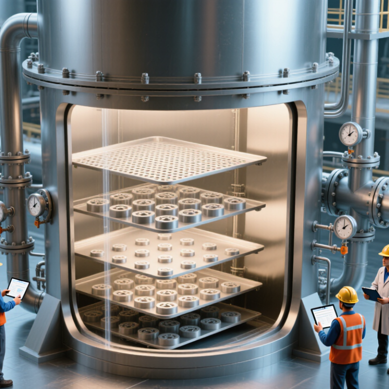
Trays create repeated vapor–liquid contact inside a distillation column. Each tray gives vapor a fresh chance to remove lighter components. Liquid moves downward, while vapor rises through openings, valves, or caps. This contact controls separation efficiency, pressure drop, and operating stability.
Tray selection begins with the process duty, not the equipment catalog. The U.S. Department of Energy’s 2015 Bandwidth Study reports that separation can consume roughly 40–70% of energy in chemical manufacturing. Small hydraulic losses therefore deserve serious attention. Sieve trays usually offer low cost and low pressure drop. Valve trays handle changing vapor loads more flexibly. Bubble-cap trays provide stronger liquid sealing, but often require higher pressure drop and maintenance.
Field reviews show that flooding is still misdiagnosed. Sometimes, the tray is not the main problem. Feed condition, fouling, poor liquid distribution, or an incorrect downcomer design may control performance. The 2023 Global Energy Review also confirms continuing pressure to reduce industrial energy demand. That pressure makes tray hydraulics increasingly important in 2026. Engineers should compare capacity, turndown, entrainment, weeping, and cleaning access. Laboratory data helps, but it is never perfect. A conservative design may protect reliability, yet it can waste valuable column space.
How to Choose the Right Distillation Column Tray in 2026?
Define the Role of Trays in Distillation Column Operation
Trays create repeated vapor–liquid contact stages inside a distillation column. The chart shows representative turndown ranges commonly used during preliminary design: the ratio between the maximum and minimum stable vapor or liquid load. Sieve trays are economical and effective at steady loads, valve trays provide broader operating flexibility, and bubble-cap trays generally offer the strongest low-load performance but require greater investment and pressure drop.
Values are typical engineering design ranges and should be verified against column diameter, pressure drop, foaming tendency, fouling risk, liquid properties, and required separation performance.
Compare Tray Types by Capacity, Efficiency, and Maintenance
Choosing a distillation tray starts with capacity, efficiency, and maintenance.
Sieve trays offer high open area and low cost. They often achieve 80–90% of the capacity of comparable valve trays. However, they can weep when vapor flow falls too low. The 2023 Gas Processing Engineering Data Book places typical tray design near 80% of flooding velocity, leaving room for surges.
Valve trays provide a wider operating range. Their movable valves respond to changing vapor rates, improving turndown and vapor-liquid contact. Practical tray efficiencies commonly range from 60% to 85%, depending on pressure, viscosity, and feed condition. Bubble-cap trays remain useful at very low vapor rates. Their liquid seal reduces weeping, but their many caps increase pressure drop, weight, and cleaning time. They are rarely the simplest choice.
Maintenance changes the real cost.
Sieve trays have fewer parts, so inspections are faster. Valve trays need checks for stuck or missing valves. Bubble-cap trays demand closer attention around caps, risers, and fouling deposits. Published design guidance supports these comparisons, but field data should decide the final selection. I would not treat efficiency ranges as guarantees. A dirty feed can overturn laboratory expectations. Tray spacing, foam behavior, and vapor distribution deserve a site-specific review before purchase. Small omissions become expensive shutdowns.
Select Tray Design for Pressure, Fouling, and Corrosion Constraints
How to Choose the Right Distillation Column Tray in 2026?
Select Tray Design for Pressure, Fouling, and Corrosion Constraints
Tray selection should begin with operating pressure, not only expected capacity. At higher pressure, vapor density increases and flooding margins can shrink. Low-pressure-drop sieve trays may protect vacuum operation, while valve trays can handle wider load changes. The U.S. Department of Energy’s Bandwidth Study on Chemical Manufacturing identifies distillation as a major energy load in chemical processing. A small pressure-drop mistake can therefore become a costly steam problem.
Fouling changes the decision. Heavy hydrocarbons, polymers, and solids can block perforations and restrict downcomers. Larger openings may resist plugging, but they can reduce turndown and entrain more liquid. Corrosion deserves equal attention. The NACE IMPACT study estimated global corrosion costs at about 3.4% of global GDP. Material selection, liquid distribution, and inspection access should match the actual contaminants, not laboratory assumptions. A perfect tray choice rarely exists. Some designs still look efficient on paper but fail after months of deposits.
Tips: Confirm fouling behavior with operating samples. Review pressure drop at minimum and maximum rates. Ask for corrosion-rate data, not guesses. Include removable panels and wash connections where maintenance history supports them. Use pilot testing for unstable feeds. The 2023 Global Energy Management System report from the U.S. Department of Energy also supports regular measurement, yet many projects still rely on design-case figures alone. That is an avoidable weakness.
Validate the Choice Through Hydraulics, Cost, and Future Operation
How to Choose the Right Distillation Column Tray in 2026?
Tray selection should begin with hydraulic evidence, not a familiar equipment preference. Calculate vapor and liquid loads at normal, minimum, and emergency conditions. Check flooding, weeping, entrainment, pressure drop, and residence time. A sieve tray may offer low cost and efficient vapor contact, but it can lose stability during low-load operation. Valve or bubble-cap designs may improve turndown, though their added parts increase maintenance demands.
Use process data from real operating windows. A column handling foaming liquid needs more disengagement space and conservative vapor velocity. Fouling feeds may require wider passages and easier cleaning access. During design reviews, compare tray spacing with expected entrainment and inspection requirements. A few extra centimeters can affect column height, steelwork, and transport costs. Small hydraulic assumptions become expensive later.
Cost validation should include energy, spares, labor, downtime, and replacement access. The cheapest tray is rarely the cheapest asset over fifteen years. Model future operation, including higher throughput, variable feed composition, stricter energy targets, and possible sensor upgrades. Digital monitoring can reveal rising pressure drop before flooding occurs, but instruments also need calibration and protection.
There is no perfect choice.
Some design margins are too generous. Others are dangerously optimistic. Recheck them with pilot data, operating history, and an independent hydraulic review. I would also challenge one uncomfortable assumption: future operators may run far below the original design rate. A tray that performs well today may become unstable after the process changes.
How to Choose the Right Distillation Column Tray in 2026? — Validate the Choice Through Hydraulics, Cost, and Future Operation
Indicative engineering comparison for preliminary design. Final selection should be confirmed with vendor-neutral hydraulic calculations, physical-property data, fouling assessment, and operating scenarios.
| Tray Type |
Typical Relative Installed CostSieve tray = 1.00 |
Practical Turndown RatioMaximum / minimum stable vapor load |
Typical Dry Pressure DropPer tray, excluding downcomer losses |
Indicative Capacity FactorF-factor, Pa0.5 |
Typical Murphree Vapor EfficiencyFor clean, well-designed systems |
Hydraulic Strengths |
Hydraulic Risks |
Fouling and Maintenance |
Best-Fit Applications |
Future-Operation Rating |
| Sieve Tray |
1.00
Lowest baseline |
2.0:1 to 3.0:1 |
3–8 mbar |
1.8–2.4 |
70–90% |
High open area; low capital cost; predictable vapor-liquid contact; relatively low pressure drop. |
Weeping can occur at low vapor rates; entrainment and flooding must be checked at high rates. |
Easy to fabricate and inspect; holes may plug when solids, polymers, or heavy fouling are present. |
Clean services with a reasonably stable throughput and moderate turndown requirement. |
Good
Excellent when operating load is stable. |
| Fixed-Valve Tray |
1.10–1.30 |
2.5:1 to 4.0:1 |
4–10 mbar |
1.9–2.5 |
75–92% |
Improved vapor distribution and lower weeping tendency than a sieve tray over a wider load range. |
Higher pressure drop and more complex fabrication; valve openings can accumulate deposits. |
Fewer loose parts than movable-valve designs; suitable for moderately clean services. |
Columns with variable feed rates where capacity flexibility is more important than minimum cost. |
Very good
Strong balance of flexibility and cost. |
| Movable-Valve Tray |
1.20–1.45 |
3.0:1 to 5.0:1 |
4–12 mbar |
2.0–2.6 |
75–93% |
Valves respond to vapor-rate changes and help maintain vapor-liquid contact during turndown. |
Moving components may stick, wear, or lose performance if deposits or corrosion products are present. |
Requires inspection of valve movement and tray hardware; maintenance access should be planned. |
Clean-to-moderately-fouling services with frequent load changes or seasonal operation. |
Very good
Useful where future throughput is uncertain. |
| Bubble-Cap Tray |
1.60–2.20 |
4.0:1 to 8.0:1 |
8–18 mbar |
1.4–2.0 |
80–95% |
Excellent liquid seal and strong resistance to vapor-rate reduction; stable operation at low vapor loads. |
High pressure drop; lower vapor capacity; greater sensitivity to hydraulic head and mechanical weight. |
Robust but expensive and labor-intensive to clean; caps and risers can foul in dirty service. |
Vacuum-sensitive systems are generally unsuitable; useful for low-load operation where liquid seal is critical. |
Conditional
Strong turndown, but energy and maintenance penalties are significant. |
| Dual-Flow Tray |
0.85–1.05 |
1.5:1 to 2.5:1 |
2–6 mbar |
1.7–2.3 |
65–88% |
Very low pressure drop; no downcomers; high active area and low tray weight. |
Limited liquid handling at low vapor rates; liquid distribution and weeping require careful design. |
Simple construction, but cleaning can be difficult because there are no conventional downcomer access paths. |
High-throughput, low-pressure-drop services with relatively steady vapor and liquid rates. |
Moderate
Efficient at design load but less tolerant of future turndown. |
Hydraulic validation checklist:
Check flooding at the maximum vapor and liquid rates; weeping and dumping at the minimum vapor rate; entrainment, downcomer backup, outlet weir loading, tray spacing, froth height, and pressure-drop limits. The listed capacity factors are indicative ranges for preliminary screening and are not substitutes for a detailed design calculation.
Cost basis:
Relative installed-cost ranges are planning indices only and exclude column shell, reboiler, condenser, instrumentation, taxes, freight, and site-specific installation conditions. Actual cost depends on metallurgy, diameter, tray spacing, access requirements, fabrication method, and regional labor rates.
Selection guide:
Choose sieve trays for clean and stable operation, valve trays for broad operating flexibility, bubble-cap trays for exceptional turndown and liquid-seal requirements, and dual-flow trays when minimum pressure drop and high active area dominate the design objective.
Conclusion
Choosing the right Distillation Column Tray is essential for achieving stable operation, efficient separation, and reliable long-term performance. The selection process should begin by defining the tray’s role in vapor-liquid contact and then evaluating feed flow rate, composition, temperature, pressure, foaming tendency, and required product purity. These factors help determine whether a sieve, valve, or bubble-cap design is most suitable for the process.
Each tray type should be compared according to capacity, separation efficiency, pressure drop, maintenance needs, and operating flexibility. The final design must also account for fouling, corrosion, mechanical strength, and potential changes in future production. Hydraulic checks should confirm that the tray can avoid flooding, weeping, entrainment, and poor liquid distribution across the expected operating range. By combining process requirements, equipment costs, maintenance considerations, and lifecycle performance, engineers can select a tray solution that supports safe, efficient, and dependable distillation column operation.