- +91-9930498858Call / WhatsApp
- [email protected]Email Us
Built strictly to custom process data sheets, ISO standards, and ASME specifications. Browse our proven equipment portfolio engineered for robust continuous operations.
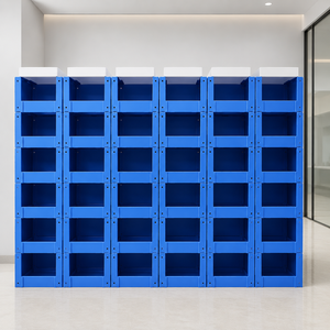
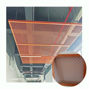
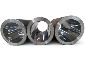
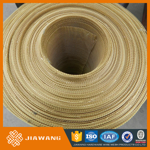
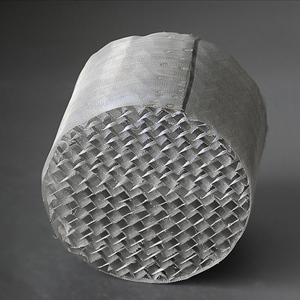
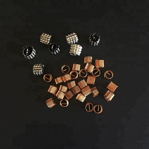
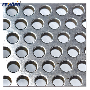
Operating continuously since 1998, Ambani Metals is an established integrated manufacturer supplying mission-critical column internals, wire gauze packings, deep-drawn components, and certified specialty alloys to over 1,000 industrial clients in 20+ export countries.
Every batch of raw stainless steel (SS304/304L, SS316/316L, 904L, Duplex 2205) and exotic superalloy (Hastelloy C-276, Monel 400, Inconel 625, Pure Nickel 200, Titanium Grade 2) is supplied with complete EN 10204 3.1 Material Test Reports (MTRs) and non-destructive Positive Material Identification (PMI).
Before metal is sheared or stamped, our process engineering desk reviews client process data sheets (PDS). We run rigorous computational hydraulic assessments to balance vapor kinetic energy factor (F-factor), liquid head losses, orifice weeping thresholds, and turndown limits across diverse operational scenarios.
Unlike simple assembly workshops, we feature multi-ton hydraulic presses, CNC laser perforators, in-house die tooling, deep drawing presses, and automated robotic TIG/plasma seam welding. This delivers unmatched dimensional precision with tolerances controlled within ±0.5 mm for tower segments.
Why initial liquid distribution dictates the operational success of structured and random packed beds: Hydraulic physics, maldistribution index (Mf), and geometry selection.
In modern fractionating, stripping, and absorption columns, structured packings (such as 250Y, 500BX, and 700CY wire gauze) provide theoretical plate heights (HETP) as low as 150 to 300 mm. However, this high mass-transfer efficiency is entirely dependent upon uniform initial irrigation at the top of the packed bed. Chemical engineering field data demonstrates that a maldistribution of just 5% to 8% in the liquid phase across the tower cross-section can degrade overall column separation efficiency by more than 30% to 50%.
When the local liquid-to-vapor ratio (L/V) deviates across column quadrants, the operating line shifts relative to the vapor-liquid equilibrium (VLE) curve. Zones with deficient liquid experience vapor bypassing (pinching), while zones with liquid accumulation experience localized hydraulic flooding. In packed beds, natural radial liquid spreading is minimal; therefore, initial maldistribution persists downward throughout the entire bed, resulting in severe HETP inflation and failure to meet product purity specifications.
Selecting the correct OEM/ODM distributor architecture requires balancing liquid viscosity, operating head, solids loading, and gas phase pressure drop. Below is an engineering comparison of the primary industrial architectures:
| Distributor Classification | Hydraulic Mechanism | Standard Drip Density | Turndown Ratio | Fouling Tolerance | Primary Column Applications |
|---|---|---|---|---|---|
| Trough-Type (Weir / Drip Tube) | Gravity feed via primary header to secondary parallel troughs; side-wall orifices or metering bottom tubes. | 80 – 180 points/m² | 3:1 to 4:1 | High (solids settle below weir level) | Refinery vacuum towers, crude fractionators, large chemical beds (>1200 mm diameter). |
| Deck / Pan-Type (Perforated Deck) | Gravity liquid pool held above deck plate; vapor risers with caps direct vapor upward while bottom holes meter liquid. | 100 – 250 points/m² | 2:1 to 3:1 | Moderate to Low (orifice plugging risk) | Small-to-medium columns (<1500 mm); pharmaceutical API stills, solvent recovery towers. |
| Pipe Lateral / Orifice Header | Pressurized closed conduit distributing liquid through downward-facing bottom orifices. | 60 – 120 points/m² | 2:1 (limited by √P head) | Low (risk of internal pipe scaling) | Wash oil zones, high vapor-velocity stripping sections, offshore floating units (motion tolerant). |
| Full-Cone Spray Nozzle Header | Hydraulic atomization through engineered swirl nozzles forming overlapping conic spray profiles. | Continuous conical coverage | 2:1 (droplet size varies with ΔP) | Moderate (nozzle orifice dependent) | Flue gas desulfurization (FGD), quenching sections, scrubber wash zones where entrainment is captured. |
For gravity-driven trough and pan distributors, the volumetric liquid flow rate ($Q$) discharged through each metering orifice is governed by Torricelli's orifice discharge equation:
Q = Cd · Ao · √(2 · g · hL)
Where Cd is the discharge coefficient (typically 0.60 – 0.62 for sharp-edged punched holes, and 0.75 – 0.82 for calibrated extruded tubes), Ao is the orifice cross-sectional area, g is gravitational acceleration, and hL is the operating liquid head above the hole center. Because flow varies with the square root of liquid height, operating with an excessively shallow liquid head (<25 mm) makes the distributor exceptionally vulnerable to column out-of-plumbness or tray tilting.
A tower out-of-level tilt of just 0.2 degrees on a 4-meter diameter shell produces a liquid level variation of ±7 mm from one side to the other. If the design liquid head is only 30 mm, this creates a 25% maldistribution between periphery nozzles. Our OEM/ODM engineering protocol resolves this by implementing dual-stage metering partitions, elevated anti-siphon side tubes, and heavy-duty adjustable leveling studs positioned on circumferential support rings.
Driven by the global energy transition, direct air capture (DAC), and circular plastic pyrolysis, column internal procurement specifications are shifting rapidly toward specialized operational paradigms.
Post-combustion CO2 capture columns (amine absorption) operate at massive column diameters (up to 8–12 meters) with unprecedented liquid loads. Procurement teams are mandating ultra-deep boxed troughs equipped with secondary multi-branch splitters designed to minimize liquid kinetic momentum and eliminate spray entrainment at the gas entrance.
EPC contractors are phasing out physical factory water testing on large-scale jobs in favor of validated computational fluid dynamics (CFD) multi-phase Eulerian simulations. OEM suppliers must provide verified digital hydraulic models proving gas velocity uniformity ($F_v$ variation < 8%) directly below the distributor.
Chemical recycling facilities processing pyrolysis oils derived from municipal plastic waste encounter high concentrations of organic acids, chlorides, and siloxanes. Sourcing has migrated away from standard SS304/316 toward Duplex 2205, Hastelloy C-276, and titanium internals with zero-tolerance for crevice corrosion.
Turnaround timelines have compressed from weeks to mere days. Buyers now demand segmented, toolless or wedge-bolted distributor assemblies engineered to pass swiftly through standard 18" (450 mm) or 24" (600 mm) vessel manways without requiring hot-work permits or internal tower welding.
Heavy oil hydrocrackers and bio-refineries demand side-weir discharge channels that actively sweep suspended particulates through overflow slots rather than bottom holes. This prevents sluggish dead zones where resinous gums and coke deposits typically initiate clogs.
Clear, unhedged answers to the most common engineering, metallurgical, and manufacturing inquiries encountered during column revamps and new-build projects.
For standard industrial installations, we recommend a minimum liquid head of 35 mm at 100% design rate, with a lower operational limit of 15 to 20 mm at minimum turndown. Operating below 15 mm introduces severe maldistribution risks because minor hydraulic waves, surface tension resistance, and structural fabrication tolerances (typically ±1.5 mm across the trough span) can cause some discharge orifices to starve completely while adjacent ones discharge erratic rivulets.
Pressure vessel shells (especially large-diameter field-erected columns) rarely conform to true circularity. Our OEM designs incorporate perimeter rim-clearance gaps (typically 25–40 mm) fitted with segmented, flexible 316L/PTFE perimeter seal wiping wipers. Furthermore, all distributor main beams and parallel trough fingers are mounted on slotted leveling jackscrews capable of ±15 mm vertical elevation adjustment, enabling the erection crew to achieve precision laser leveling within ±1 mm across the entire cross-section regardless of support-ring welding distortions.
Multi-stage systems (combining a primary parting box with secondary distribution troughs) are mandatory when column diameter exceeds 1,200 mm, or when the liquid inlet velocity through the column feed nozzle creates sufficient kinetic momentum to cause wave sloshing in an unbaffled tray. A parting box dissipates the kinetic energy of the incoming fluid stream, de-aerates two-phase flash vapor, and divides the liquid into perfectly metered volumetric fractions before introducing it smoothly to the secondary lateral troughs.
For aggressive environments requiring Hastelloy C-276, Inconel 625, or Monel 400, our automated welding processes strictly control heat input through continuous pulsed TIG welding and pure trailing argon back-purging. This prevents alloy element segregation, chromium depletion, and carbide precipitation in the heat-affected zone (HAZ). All finished welded sub-assemblies are fully passivated via acid immersion baths according to ASTM A380 specifications and tested with liquid dye penetrant inspection.
Every export shipment is accompanied by a comprehensive Quality Dossier containing: (1) As-Built General Arrangement (GA) and segment assembly drawings; (2) EN 10204 3.1 Material Test Reports for all pressure and non-pressure components; (3) Positive Material Identification (PMI) verification records; (4) Hydrostatic and dimensional factory inspection certificates; and (5) Seaworthy export packaging manifests detailing piece marks corresponding directly to tower installation tags.
Send your Process Data Sheet (PDS), vessel fabrication drawings, or column revamp parameters directly to our senior mass transfer engineering desk. We provide hydraulic simulations, budget quotations, and turnkey manufacturing schedules within 24 hours.