
Engineering White Paper: Mechanical Design & Fluid Dynamics of Bed Limiters in Packed Towers
In continuous counter-current gas-liquid mass transfer columns, packed beds represent the heart of separation efficiency. However, operational upsets such as vapor surges, rapid depressurization, foaming, or cyclic flooding can generate hydraulic uplift forces exceeding the natural gravitational settling force of the packing elements. Without structurally verified bed limiters (for random packing) or hold-down plates (for structured packing), these dynamic forces cause bed fluidization, high-velocity particle attrition, micro-fracturing of ceramic/carbon components, severe entrainment of packing fragments into overhead condensers, and disastrous destruction of expensive liquid distributors.
As an authoritative global manufacturer serving the Vietnamese heavy chemical and petrochemical corridors, our bed limiter systems are mechanically calculated using rigorous boundary condition models. Our design protocols incorporate the upward aerodynamic drag force calculated via modified Ergun equations, turbulent kinetic energy vectors, and mechanical structural beam deflection under worst-case two-phase pressure drops (ΔP > 1200 Pa/m). By guaranteeing a net free cross-sectional open area between 85% and 96%, our bed retention systems impose virtually zero parasitic hydraulic resistance, safeguarding nominal capacity and maintaining uniform vapor redistribution across column diameters up to 12 meters.
Critical Engineering Principle: A bed limiter is not merely a physical barrier; it is an aerodynamically neutral restraint. Any constriction below 80% free area induces premature localized flooding, boundary layer separation, and vapor jetting that de-entrains liquid downward while accelerating gas velocities toward the column wall.
Structural Classification: Bed Limiters vs. Hold-Down Plates vs. Support Grids
Procurement engineers often confuse hold-down plates and bed limiters. While both are upper-boundary internals, their mechanical duty and installation geometries differ radically:
| Equipment Type | Primary Target Bed | Design Net Free Area | Mounting Mechanism | Uplift Design Rating |
|---|---|---|---|---|
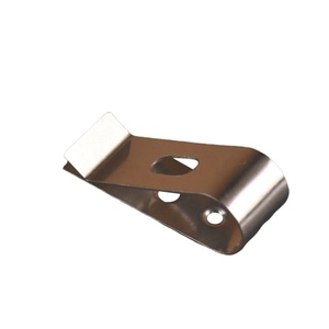
| Random Bed Limiter | Metal, Ceramic & Plastic Random Packing (Pall, Raschig, Saddle Rings) | 85% – 95% | Resting directly on bed or clamped to vessel wall ring / spider clips | 750 – 2,500 N/m² (Surge Resistant) |
| Structured Hold-Down Plate | Corrugated Gauze / Sheet Metal Structured Packing | 88% – 96% | Segmented beam system bolted to column wall brackets | 1,200 – 4,500 N/m² |
| Catalyst Bed Retainer | Fixed Catalyst Pellets, Molecular Sieves, Desiccant Beads | 65% – 80% (Multi-layer Fine Screen) | Heavy-duty tie rods and load-bearing perimeter rings | 5,000 – 15,000 N/m² |
| High-Load Support Grid | Base Support for all Packing & Operating Liquid Holdup | 100% – 125% of Column Area | Ledge rings, major structural beams, downcomer clamps | 15,000 – 60,000 N/m² (Dead Load) |
Mechanical Metallurgy for Severe Environments
Vietnam's coastal refining installations and tropical monsoon humidity dictate stringent metallurgical discipline. Our manufacturing facility processes certified austenitic stainless steels (AISI 304, 304L, 316, 316L), duplex alloys (2205, 2507) for stress-corrosion cracking immunity in chloride-rich brackish environments, and nickel superalloys (Hastelloy C-276, Inconel 625, Monel 400) for highly aggressive sour gas, hydrofluoric acid, or chlor-alkali processes. All raw materials are verified using Optical Emission Spectrometry (OES) and Positive Material Identification (PMI), accompanied by EN 10204 3.1 inspection certification.