- +91-9930498858Call / WhatsApp
- [email protected]Email Us
From fractionation distillation trays and structured gauze packing to auxiliary filtration elements and heavy-duty enclosures, our manufacturing lines adhere strictly to ISO 9001, ASME Section VIII, and global engineering specifications.
Fractionation column trays are the thermodynamic and hydraulic foundation of modern vapor-liquid separation units. Whether executing crude oil atmospheric distillation, vacuum residue fractionating, ethylene cryogenic rectification, or fine pharmaceutical solvent recovery, selecting the right tray architecture directly impacts column throughput, separation efficiency, and energy consumption. As a premier Chinese manufacturer and global supplier, we combine decades of metallurgical expertise with rigorous computational fluid dynamics (CFD) to deliver trays engineered for minimum pressure drop, maximum turndown ratio, and prolonged operating cycles.
Separation columns function under intricate phase dynamics where the vapor phase ascends through active perforations while liquid sweeps across the tray deck toward the downcomer. If vapor velocity exceeds design limits, entrainment flooding and jetting occur, entraining liquid droplets to the stage above and collapsing fractionating purity. Conversely, insufficient vapor velocities cause weeping or dumping, allowing liquid to leak through active tray perforations rather than following the prescribed hydraulic path through the downcomers. Our engineering protocol addresses these delicate fluid dynamics across every manufactured tray assembly.
Different chemical systems require distinct active area geometries. Our fabrication facility manufactures a complete range of fractionation column internals tailored to process requirements:
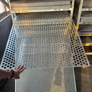
Characterized by plain perforated metal decks with engineered hole diameters (typically 3mm to 12.7mm). Sieve trays deliver low capital cost, predictable hydraulics, and straightforward maintenance. Ideal for clean petrochemical services with steady throughput and low load swings.
Equipped with permanently pressed or extruded caps integrated into the tray deck. Fixed valve designs eliminate moving mechanical components, resisting fouling and valve leg popping while providing broad vapor deflection and extended operational lifespans under corrosive conditions.
Feature discrete metal caps that lift dynamically in response to varying vapor flow rates. This variable-orifice action maintains high interfacial turbulence and uniform vapor distribution, delivering exceptional turndown ratios of up to 4:1 to 5:1 without liquid weeping.
Incorporate riser chimneys covered by slotted bell caps with liquid-tight seals. Bubble cap trays maintain an absolute liquid level on the deck even during complete vapor shutoff, making them the industry standard for reactive distillation, wash columns, and minimal-liquid systems.
Engineered with truncated downcomers, canted outlet weirs, and directional louvers to expand the active bubbling area by up to 25%. These designs mitigate vapor cross-flow channeling and prevent early downcomer backup during plant debottlenecking revamps.
Non-downcomer designs where vapor and liquid simultaneously pass through identical deck perforations or cascading segment showers. Engineered specifically for severely fouling slurries, coking environments, and heavy petrochemical cracker quench towers.
Selecting between sieve, valve, bubble cap, or high-capacity internals requires evaluating hydraulic performance parameters against capital expenditure and maintenance requirements. The following reference data summarizes key operational metrics:
| Tray Architecture | Typical Turndown Ratio | Pressure Drop (ΔP/tray) | Separation Efficiency | Fouling Resistance | Relative Fabrication Cost |
|---|---|---|---|---|---|
| Standard Sieve Tray | 1.8:1 - 2.0:1 | Low to Moderate (3-6 mbar) | Standard Baseline (70-85%) | Moderate | Low (1.0x Baseline) |
| Fixed Valve Tray | 2.8:1 - 3.2:1 | Moderate (4-8 mbar) | High (80-90%) | Very High | Moderate (1.2x Baseline) |
| Moving / Floating Valve | 4.0:1 - 5.0:1 | Moderate (5-9 mbar) | Very High (85-92%) | Moderate (prone to sticking) | Moderate-High (1.4x Baseline) |
| Bubble Cap Assembly | 10:1 (Infinite Seal) | High (8-14 mbar) | High (75-85%) | Low (chimney sludge trap) | High (2.5x - 3.5x Baseline) |
| High-Performance Louvered | 3.5:1 - 4.5:1 | Low (3-5 mbar) | Superior (90-95%) | High | Specialty (1.8x - 2.2x Baseline) |
| Dual-Flow Perforated | 1.3:1 - 1.5:1 | Very Low (2-4 mbar) | Lower (55-65%) | Extremely High (Self-Cleaning) | Lowest (0.8x Baseline) |
Chemical processing conditions expose mass transfer internals to severe physical and chemical stresses, including chloride stress corrosion cracking (SCC), hydrogen embrittlement, sulfidic corrosion, organic acid attack, and high-velocity erosion. As an integrated manufacturer, our production lines maintain end-to-end quality control and strict raw material traceability.
Standard fabrication relies on austenitic stainless steels (AISI 304, 304L, 316, 316L), offering dependable corrosion resistance and weldability across atmospheric columns and light organic fractionators. For demanding chemical services involving concentrated chlorides, amines, sour water, or nitric acid, our shop fabricates in Super Austenitic (904L), Duplex 2205, and Super Duplex 2507 alloys. These dual-phase microstructures combine yield strengths exceeding 450 MPa with pitting resistance equivalent numbers (PREN) above 42.
For aggressive halide environments, seawater processing, hydrochloric streams, and high-temperature petrochemical cracking, we maintain certified fabrication lines for nickel-based and non-ferrous superalloys:
Global procurement dynamics for process internals are evolving as the energy transition accelerates. Industrial plant operators, EPC firms, and revamping engineers increasingly emphasize three core priorities:
Global carbon capture, utilization, and storage (CCUS) projects require high-efficiency, low-pressure-drop columns. Modern procurement centers on mass transfer internals that minimize fan power and steam consumption in post-combustion amine regeneration units.
Procurement teams increasingly evaluate Total Cost of Ownership (TCO) over basic component price. High-capacity trays that resist fouling extend continuous run-times between turnarounds from 3 to 6 years, delivering substantial lifetime economic savings.
Downtime during planned shutdowns costs millions. Buyers require modular tray sections designed to pass smoothly through existing vessel manways (DN450 to DN600), utilizing self-locking clamps and pre-welded truss beams to reduce install times by 30%.
The distillation sector is evolving rapidly to address challenging separations, heat-sensitive compounds, and high-purity chemical requirements. Several emerging technologies are reshaping the industry:
1. Divided Wall Columns (DWC): Integrating vertical dividing partition walls within a single column shell allows three or more pure fractions to be separated in a single unit. DWC installations cut capital costs by 30% and operational energy consumption by up to 35% compared to conventional two-column trains. Manufacturing DWC trays requires tight planar tolerances and custom downcomer seals across the dividing wall boundary.
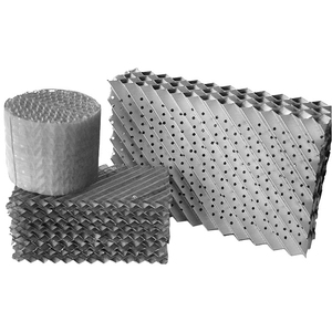
2. Hybrid Internals (Tray-to-Packing Combinations): Modern debottlenecking strategies combine mass transfer technologies. Heavy solids-bearing sections and wash zones employ fouling-resistant fixed valve trays, while rectification and vacuum fractionation zones utilize high-surface structured gauze packing. This hybrid design balances high vapor capacity with minimal HETP (Height Equivalent to a Theoretical Plate).
3. Advanced Surface Treatments: Specialized coatings and mechanical finishes, such as electropolishing to Ra < 0.4 µm, minimize nucleation points for polymer buildup in butadiene, styrene, and acrylic acid columns. Specialized surface micro-texturing also improves liquid spread across active decks under ultra-low liquid load conditions.
For more than 25 years, our manufacturing and engineering teams have served tier-one chemical refineries, EPC contractors, and equipment packagers across 20+ countries, including the United States, UAE, Saudi Arabia, Germany, Canada, and Australia. Our operational strengths include:
Our workshop houses high-tonnage precision punching presses, fiber laser cutting centers, CNC turret presses, and automated stamping lines, maintaining tolerances within ±0.2 mm across column diameters ranging from 400 mm to over 10 meters.
Every shipment includes EN 10204 3.1 material test certificates (MTC), positive material identification (PMI) analysis, weld inspection records, and full dimensional inspection sheets. Third-party inspections (SGS, TÜV, Bureau Veritas) are welcomed.
All tray panels, support trusses, downcomer aprons, and hardware sets are laser-etched with piece-marks corresponding to tray layout drawings, packed in desiccated, heat-treated wooden crates for secure global transit.
Direct technical answers to common questions from plant process engineers, revamp managers, and procurement officers:
Floating valve trays provide broader operating flexibility, delivering up to a 5:1 turndown ratio by dynamically opening and closing with variable vapor rates. However, moving valves are susceptible to sticking or popping out in polymerizing, dirty, or corrosive streams. Fixed valve trays eliminate moving parts, making them practically foul-proof and structurally rigid while still maintaining a 3:1 turndown—making them the superior option for heavy feedstocks, vacuum residue fractionators, and corrosive systems.
To deliver an accurate hydraulic design and commercial proposal, our engineering team requires: internal column diameter (ID), tray spacing (typically 450mm to 600mm), total number of trays, vapor and liquid mass flow rates (minimum, normal, design), operating pressure and temperature, fluid densities, viscosities, surface tensions, preferred metallurgy, and existing manway dimensions for internal installation entry.
Yes. We specialize in revamps and drop-in replacements. By reviewing existing column vessel drawings, we design tray deck panels, downcomer bolt bars, and clamping arrangements that mount directly onto existing support rings and downcomer bolting clips without needing inside welding, stress-relieving, or shell hydrotesting.
Downcomer choke flooding occurs when liquid velocity through the downcomer apron exceeds clear liquid disengagement capability, or when downcomer froth backup rises above the outlet weir. We engineer downcomers with calculated top-to-bottom sloped geometry to maximize deck active area, size clear liquid downcomer clearance heights properly, and verify that total downcomer backup remains under 50% of the overall tray spacing.
Because we maintain dedicated coil stocks of SS304L, SS316L, and high-performance alloys alongside integrated CNC punching centers, standard lead times for complete tray replacement orders range from 4 to 8 weeks, depending on diameter and tray count. Emergency replacement orders for plant shutdowns can be fast-tracked to ship within 10 to 14 days.
Speak directly with our mass transfer engineering division. Send us your column process data sheet, equipment drawings, or revamp specifications for hydraulic validation and competitive manufacturing proposals.